
This tutorial covers the Sweatt model of diffractive optics. It also teaches how to make a simple prism by using coordinate breaks, and how to use the index plotter to verify the variation of refractive index with wavelength.
Introduction
The Sweatt model is a way to describe diffractive optics like gratings, kinoforms, or holographic surfaces, using only standard refractive surfaces like planes, spheres, and aspheres. The idea is to replace the diffracting surface with a very thin lens of a material of very high refractive index, to achieve the same ray deflection and phase shift.
For example, consider a grating that diffracts light of d wavelength (587.56nm) through an angle of 5 degrees. This grating can be modelled as a thin prism whose refractive index is 10000 and whose apex angle is 0.0005 degrees. The large value of the refractive index ensures that large ray deflections result from even small thickness variations. Because the prism is nearly zero thickness, the ray enters and leaves the prism with negligible change in position.
Setting up the geometry
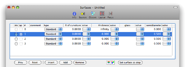
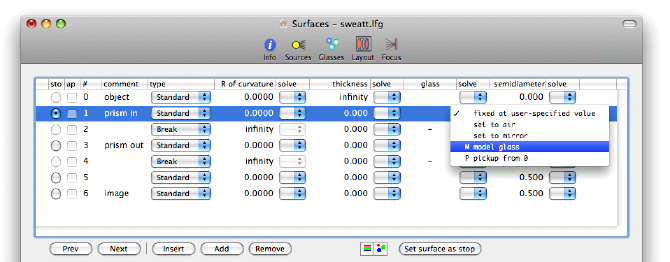
To enter the Sweatt model for this grating in LensForge, open a new document and on the surface data editor create four surfaces. Set the thickness of surface 0 to infinity, and set the stop at surface 1. You should have this:
At this point we can save the document as LensForge document called "sweatt".
To turn surface 1 into a prism, we are going to replace it by four surfaces:
- Prism entrance surface
- Coordinate break to tilt prism exit surface
- Prism exit surface
- Coordinate break to restore system axis
A coordinate break is nothing more than a way to specify position and orientation of following surfaces relative to the surface just before the coordinate break. Coordinate breaks have no effect on rays: they are pure geometry.
To create three new surfaces after surface 1, we select surface 2 and insert three surfaces in front of it by pressing the "Insert" button three times.
The prism exit is now surface 3, and we surround it by coordinate breaks, in order to tilt it. Use the popup menus in the surface type column to set the type of surfaces 2 and 4 to "Break".
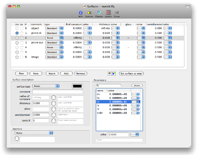
Select sufrace 2 (which is a break), and on the Parameters table enter 5e-4 for the rotation angle rx.
For those unfamiliar with the "e" notation of scientific notation as used in computer programming, 5e-4 is 0.0005, that is, 5 divided by ten thousand.
Now you should have the following:
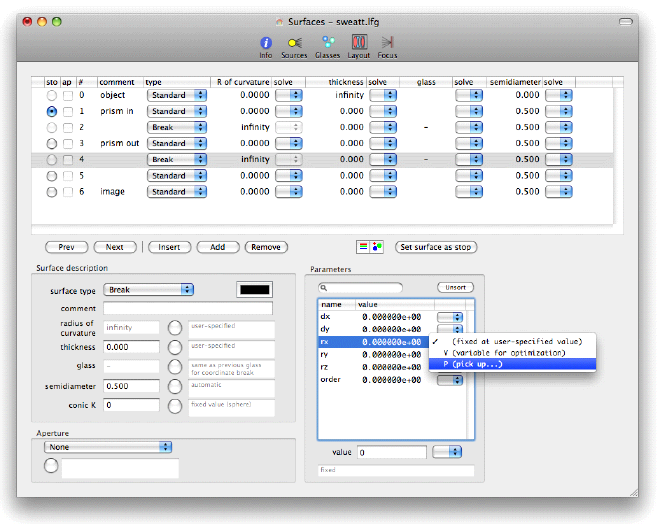
We want the coordiante break at surface 4 to undo the effect of the coordinate break at surface 2. We could just enter -5e-4 for the rx parameter of break 4, but it is better to use a pickup so that the rx parameter of break 4 will be the negative of break 2, even if we change it. To do this we select surface 4 and on the parameter table select the rx parameter. Then use the popup menu for rx to select pickup, like this:
On the Pickup specification sheet that appears, the pickup surface will be set to surface 2 (the only surface suitable for a parameter pickup). Set the scale factor to -1, and you'll see the following:
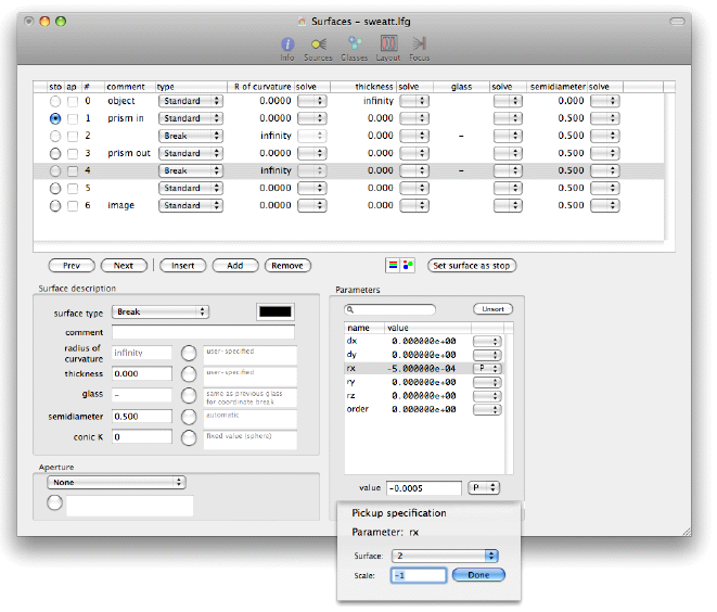
Press the "Done" button on the Pickup specification sheet to dismiss the sheet.
Setting the model glass
So far we have set up a prism whose thickness at the optical axis is zero and whose exit surface is tilted at a very small angle. But all the materials are air so the prism will not deflect rays at all. Now we need to set the material of the prism to a Sweatt model glass, that is, a glass with a large refractive index and a special Abbe V-value. To do this select surface 1 (the prism entrace face) and use the popup menu in the glass solve column to set the glass to "Model glass".
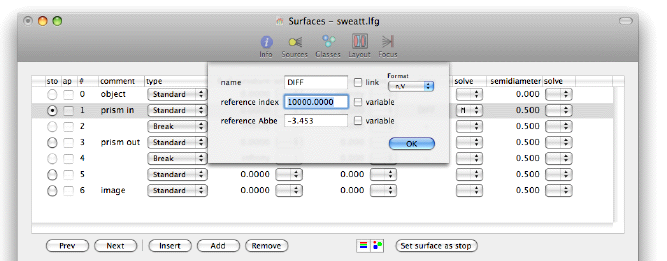
On the model glass parameter sheet that appears, enter the following parameters for the model glass:
| Parameter | Value |
|---|---|
| Name | DIFF |
| Index | 10000 |
| Abbe | -3.4534 |
For a model glass the "reference index" is the refractive index at d wavelength (587.56nm). The particular negative value of the Abbe V-value that we have entered ensures that the refractive index of the glass is proportional to the wavelength.
Press the "OK" button on the sheet to dismiss it.
Verifying the glass
Our goal in the previous section was to make a model glass whose refractive index varies proportionally to the wavelength. Did we succeed? Let's use the Index Plotter tool of LensForge to see. The procedure is:
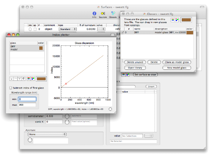
- Click on the "Glasses" icon on the toolbar of the surface data window to get a "Glasses" window that shows the glasses that are in use by the lens design.
- Use the menu item Tools > Index plotter to summon the index plotter window.
- Drag the glass "DIFF" from the table of glasses on the "Glasses" window to the table on the index plotter.
- Set the minimum wavelength of the wavelength range to zero.
Now we can see that the refractive index is, in fact, proportional to the wavelength (because the plot is a straight line that passes through the origin):
We are finished with the Glasses window and Index plotter, you can close them now.
Setting up wavelengths of light
Press the "Sources" button on the toolbar of the surface data window to summon the Sources window. Press the "Use FdC" button to set up standard F, d, and C wavelengths.
Studying the deflection of light by the "grating"
To examine the deflection of rays we can use the spot diagram, chosing the origin to be the y-momentum:
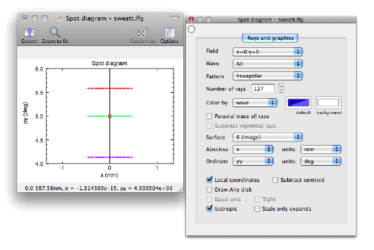
Note that it is necessary to uncheck the "Subtract centroid" checkbox, since otherwise the centroid is subtracted for each field point.